In modern manufacturing, healthcare, and precision electronics, the ultrasonic cleaner has become more than just a useful device—it’s a precision cleaning system powered by highly refined mechanical principles. Most users are familiar with the sparkling results these machines produce, but far fewer understand what happens beneath the surface. Knowing the mechanical process behind ultrasonic cleaning not only deepens appreciation for its effectiveness, but also enables smarter equipment use, better maintenance decisions, and cleaner outcomes.
How Ultrasonic Cleaning Mechanically Works
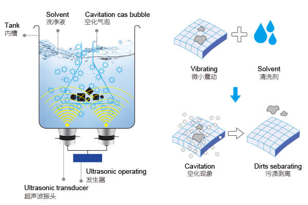
At the heart of every ultrasonic cleaner lies a fascinating physical process known as cavitation, and the mechanical journey begins the moment the system is powered on. The ultrasonic generator first converts standard AC electricity (typically 220V/50Hz) into high-frequency electrical signals ranging between 20 kHz and 400 kHz. These signals are highly stable and energetic, ideal for the next transformation stage.
The high-frequency signals are then transmitted to the transducer—the mechanical core of the system. Usually made from high-quality piezoelectric ceramics, the transducer converts this electrical energy into rapid mechanical oscillations. These vibrations, occurring tens or even hundreds of thousands of times per second, are passed directly to the base of the cleaning tank.
Once the oscillations reach the liquid in the tank (often water or a water-based solution), they initiate a rapid series of compression and rarefaction cycles, creating alternating high-pressure and low-pressure zones. In the low-pressure zones, microscopic bubbles form in the fluid. These bubbles expand, collapse, and release immense, localized energy in an event called cavitation collapse.
These micro-explosions generate localized temperatures of thousands of degrees Celsius and pressures reaching hundreds of atmospheres—but all within a fraction of a second. This intense energy burst dislodges contaminants like oil, oxide, dust, and biofilm from every surface, gap, or blind hole of the submerged object without physically touching it.
Frequency also plays a key role in how aggressive or gentle the cleaning is.
Low frequencies (20–40 kHz) deliver strong cavitation and are ideal for coarse, oily, or industrial parts.
Medium frequencies (40–80 kHz) offer balanced cleaning for electronics, optics, and moderate contaminants.
High frequencies (100 kHz or above) produce extremely fine bubbles, ideal for cleaning delicate items like semiconductor wafers, microelectronics, or fine jewelry.
Inside the Machine: Core Mechanical Components
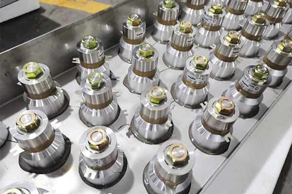
An ultrasonic cleaner’s performance hinges on the precision of its mechanical components. Chief among them is the ultrasonic transducer. This device, made from layers of piezoelectric ceramic, must be engineered to specific thicknesses and tuned to resonate perfectly with the frequency from the generator. Industrial-grade transducers are secured using robust bonding materials and mounted for maximum energy transfer.
The cleaning tank is typically constructed from SUS304 stainless steel, known for its corrosion resistance and thermal durability. Many tanks are produced using one-piece stamping to eliminate weld seams, reducing the risk of leaks or deformation over time. The interior is often polished or electro-polished to improve reflectivity and cavitation efficiency by minimizing friction and impurity retention.
The outer chassis is designed to withstand long-term mechanical stress. It’s often assembled using argon welding, pressed steel treatments, and precision alignment processes. These ensure that vibration remains contained, machine integrity is preserved, and user safety is never compromised.
Modern ultrasonic cleaners often include a digital control panel, where mechanical buttons meet electronic interfaces. Users can set temperature, timer, and power levels. Some systems also feature filtering units, degassing functions, or automated drying systems—all of which are integrated into the mechanical-electronic infrastructure.
Precision in Manufacturing: How It’s Built to Perform
Every step in the construction of an ultrasonic cleaner is guided by engineering logic. The transducer is bonded and aligned using controlled heating processes and frequency testing. Its resonance must match the signal generator with high precision, or energy transfer and cleaning power will be inefficient.
The cleaning tank is not just a container—it’s a mechanical medium. Its wall thickness is calculated to ensure even vibration distribution across the tank surface, with reinforcement points where higher energy loads are expected. Tanks for industrial use may also include thermal insulation, multilayer supports, and frequency stabilization features.
The machine casing is designed not only for durability but also for vibration damping. Internal layouts are tested under long-term resonance to confirm that no structural fatigue or frequency drift occurs under prolonged use. Some industrial units undergo hundreds of hours of load testing before being approved for sale.
From Start to Finish: The Mechanical Cleaning Workflow
Ultrasonic cleaning isn’t just a single vibration step—it’s a complete workflow, especially in high-grade industrial or medical use. The sequence generally follows:
For water-based systems:
Objects are loaded into baskets, then submerged in a heated cleaning tank. An initial cavitation cycle removes surface contaminants. If necessary, a spray rinse removes loosened particles. A second ultrasonic cycle may follow to target fine impurities. Final rinsing ensures no chemical residues remain. The parts are then dried using warm air or vacuum systems.
For solvent-based systems, especially in cleanroom or aerospace industries:
Parts are placed in vacuum-sealed ultrasonic tanks. Cleaning occurs under reduced pressure, improving penetration into micro-crevices. This is followed by vacuum rinsing, vacuum drying, and solvent recovery. These closed-loop systems ensure safety, environmental compliance, and maximum solvent reuse.
Each stage must be mechanically synchronized to ensure energy flow is uninterrupted and that delicate parts aren’t overexposed. Valve systems, temperature control relays, and tank vibration dampers all operate in coordinated sequence.
Optimizing Mechanical Parameters for Best Results
To get the most out of ultrasonic cleaning, key mechanical parameters must be fine-tuned:
Frequency should match the material and contaminant type.
Power density needs to be high enough to achieve cavitation without damaging the item.
Temperature typically ranges from 40–60°C, which enhances cleaning without degrading delicate surfaces.
Cycle time should be adjusted based on the item’s surface complexity and contamination level.
Liquid depth and object positioning within the tank also affect how evenly the energy is distributed.
Fine-tuning these variables helps strike a balance between aggressive cleaning power and material safety.
Engineering Cleanliness: A Technological Achievement
Ultrasonic cleaning is more than high-frequency bubbles—it’s a marvel of mechanical engineering, material science, and system coordination. Each component, from the transducer to the tank, plays a precise role in turning electrical impulses into thorough, damage-free cleanliness.
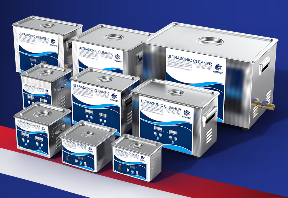
Granbo ultrasonic cleaners represent this integration of mechanical precision and industrial-grade durability. Their systems are built using advanced fabrication techniques, reinforced stainless components, and frequency-matched transducers to ensure long-term performance. From compact lab models to large-scale production units, Granbo cleaners are engineered to perform, cycle after cycle, with the mechanical integrity needed in today’s demanding environments.
Understanding the mechanical process behind ultrasonic cleaning allows professionals to optimize cleaning protocols, improve equipment longevity, and maintain the highest levels of operational hygiene. It’s not just a cleaning method—it’s precision engineering in motion.